Low-power firmware: sleep modes, wake sources and measuring µA
A battery device’s lifetime is decided almost entirely by what the firmware does between the useful moments — the 99.9% of the time it should be doing nothing at all. Get that wrong and a coin cell lasts a week; get it right and the same cell lasts years, on the same hardware. The difference is never a faster algorithm; it’s keeping the MCU in its deepest safe sleep for as long as possible, waking only on a real event, and proving it with a real measurement. Let’s make that concrete.
It’s the area under the curve
Plot current against time for a typical sensor node and the shape tells the whole story: brief, tall spikes of activity separated by long, flat stretches of sleep.
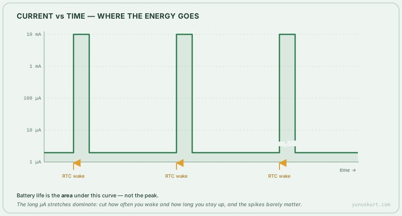 Figure 1 — The duty-cycle that defines battery life. The peaks look dramatic, but it’s the long µA valleys — and how often you leave them — that drain the cell.
The energy used is the integral of current over time, so on this curve the area is what matters, not the height of any spike. A 10 mA spike that lasts 10 ms costs 0.1 mA·s; sitting at 2 µA for 3 seconds costs 6 µA·s — but you do the second thing all the time. That’s why the two levers that matter are: how deep you sleep between events, and how often and how long you wake. Shaving a wakeup from 50 ms to 5 ms, or from once a second to once a minute, beats almost any optimisation of the active code.
The low-power modes — and what each costs you
Every MCU offers a ladder of sleep modes. Each step down saves more current but turns off more of the chip, so you wake more slowly and lose more state. On STM32 the rungs are Sleep, Stop, Standby and Shutdown:
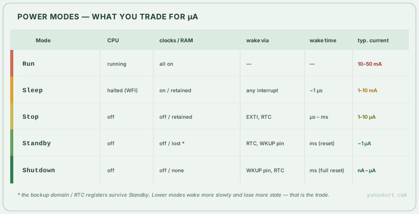 Figure 2 — The trade is always the same: deeper modes draw less but keep less alive and wake more slowly. Pick the deepest mode whose retained state and wake latency your application can tolerate.
The decision is mostly about what state you can afford to lose and how fast you must wake:
- Sleep stops the CPU (
WFI/WFE) but leaves clocks and peripherals running, so a DMA transfer or a timer keeps going and any interrupt wakes you in ~1 µs. This is the default “idle” — pair it with DMA so the core sleeps while data moves, and with an RTOS idle hook so it sleeps whenever no task is ready. - Stop turns the clocks off but retains RAM and registers, so you resume exactly where you were, woken by an EXTI line or the RTC. This is the workhorse for a battery node: single-digit µA, but your context survives.
- Standby powers down the core domain — RAM is lost (only the small backup domain and RTC survive). You wake via a wake pin or the RTC, but it’s effectively a reset, so you re-run startup and rebuild state.
- Shutdown is the deepest: even the regulator is off, nA-class current, wake only from a pin or RTC, full reset on wake.
A good rule: live in Stop between events if you need your state and fast-ish wakeups, and drop to Standby/Shutdown only for very long idle periods where a reset-on-wake is acceptable.
Wake sources: the other half of the design
Sleeping is easy; waking correctly is where designs fail. A device is only as low-power as its wake plan:
- RTC — the alarm/wakeup timer keeps running in Stop and Standby on a ~µA clock, so it’s how you do periodic work (“wake every 60 s, sample, sleep”).
- EXTI / GPIO interrupt — wake on an external event (a button, a sensor’s data-ready line, an accelerometer’s motion interrupt). This is what makes event-driven designs beat polling ones: don’t wake to check, let the event wake you.
- Wake pins — dedicated pins that pull the chip out of Standby/Shutdown.
- Peripheral wake — a UART or I²C that can wake the CPU on an address match or start bit, so a comms peripheral can stay armed while the core sleeps.
The trap is a stray peripheral or pin left enabled that keeps waking you — or worse, a floating input drawing current. Every µA of “why is it not sleeping?” is usually one forgotten clock, one enabled peripheral, or one pin not configured to a defined state before sleep.
Measuring it — where a multimeter lies
You cannot optimise what you can’t measure, and battery current is genuinely hard to measure because it spans five or six decades — from nA in Shutdown to tens of mA in a radio burst — often within the same second.
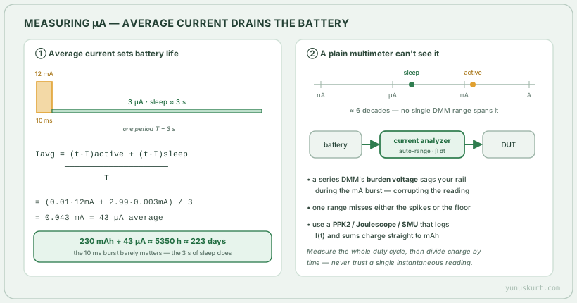 Figure 3 — Battery life is set by average current over the whole duty cycle, and measuring it needs an instrument that spans nA to mA and integrates charge — not a single multimeter reading.
What actually matters is the average current over a full duty cycle:
For the example above — a 12 mA, 10 ms burst once every 3 s, sleeping at 3 µA — the average is about 43 µA, so a 230 mAh coin cell lasts roughly 223 days. Notice the active burst contributes almost nothing; the sleep floor dominates. Two consequences for measurement:
- A series multimeter is the wrong tool. Its burden voltage (the drop across its internal shunt) sags your supply rail exactly during the mA burst, changing the thing you’re measuring; and no single range covers nA and mA, so you either miss the spikes or can’t see the floor.
- Use a current analyzer — a Nordic Power Profiler Kit, a Joulescope, or a
source-measure unit. They auto-range across the decades, log
I(t), and integrate charge so you read out actual mAh per hour or per event. Measure the whole cycle, divide charge by time, and that number predicts battery life.
Field notes
- Optimise the duty cycle before the active code. Halving wake frequency or wake duration beats almost any code optimisation — it’s the area under Figure 1.
- Default the idle path to the deepest mode you can resume from, usually Stop, and only stay in Sleep when a peripheral must keep running.
- Configure every pin before sleeping. Floating inputs and forgotten pull-ups are the most common “stuck at hundreds of µA” cause; an enabled but unused peripheral clock is the second.
- Be event-driven, not polling. Let an EXTI or sensor interrupt wake the MCU instead of waking on a timer to check — that single change often dwarfs everything else.
- Measure with the right instrument, over a full cycle. A number from a multimeter held during sleep is meaningless; charge-per-cycle from a current analyzer is the truth. Add a wireless radio and this matters even more — TX bursts are the tallest spikes you own.